Mini AMR
At EKC
2022.01 - 2022.09.
The development of a demonstration and training robot.
Professional level: work, Project volume: great
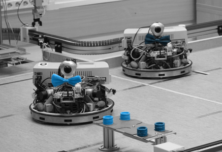
The project was comissioned by SZTAKI. Their portfolio consists of among other things education, demonstration and research. They have a laboratory with a simulated modern factory plant. I also spent two semesters in this lab, one working on a semester project and one completing my thesis work.
In this lab there is a big table with robot arms, automated storages and most important for us, AGVs. They required a replacement robot to the ones they had for years before. Those robots required a lot of maintenance and were less reliable than expected, required parts that were not in production anymore and their upgrades were difficult to implement because of their relatively closed architecture.
Their function is to move simulated parts aka. workpieces from one spot to another. They should complete this task as independently as possible. High level implementation has no limit. One could say optimal solution would be an AI that know what it wants to do how and when. The new robot were to solve all the tasks the old ones did, while fixing their problems too.
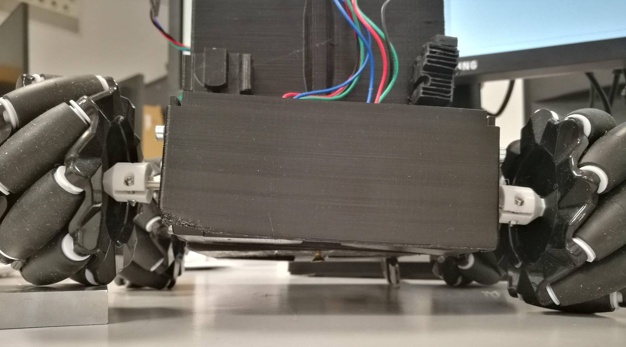
My first task at this company was to design an print a basic body that solves one of the requirements, that is to be able to traverse uneven ground. I designed a partially independent suspension. The frond and back axes can rotate relative to each other.
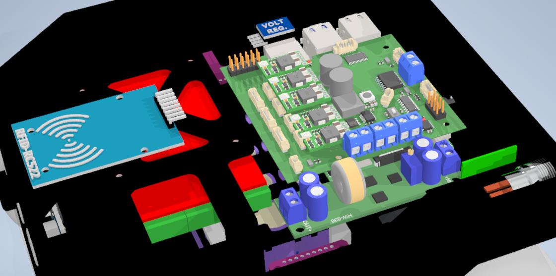
My design was not the first in the company though and I inherited the electronics. This was an arduino UNO with a CNC shield. This shield is the red board on the image above. Later I expanded on this electronics and almost completely replaced it in a few steps.
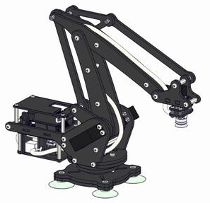
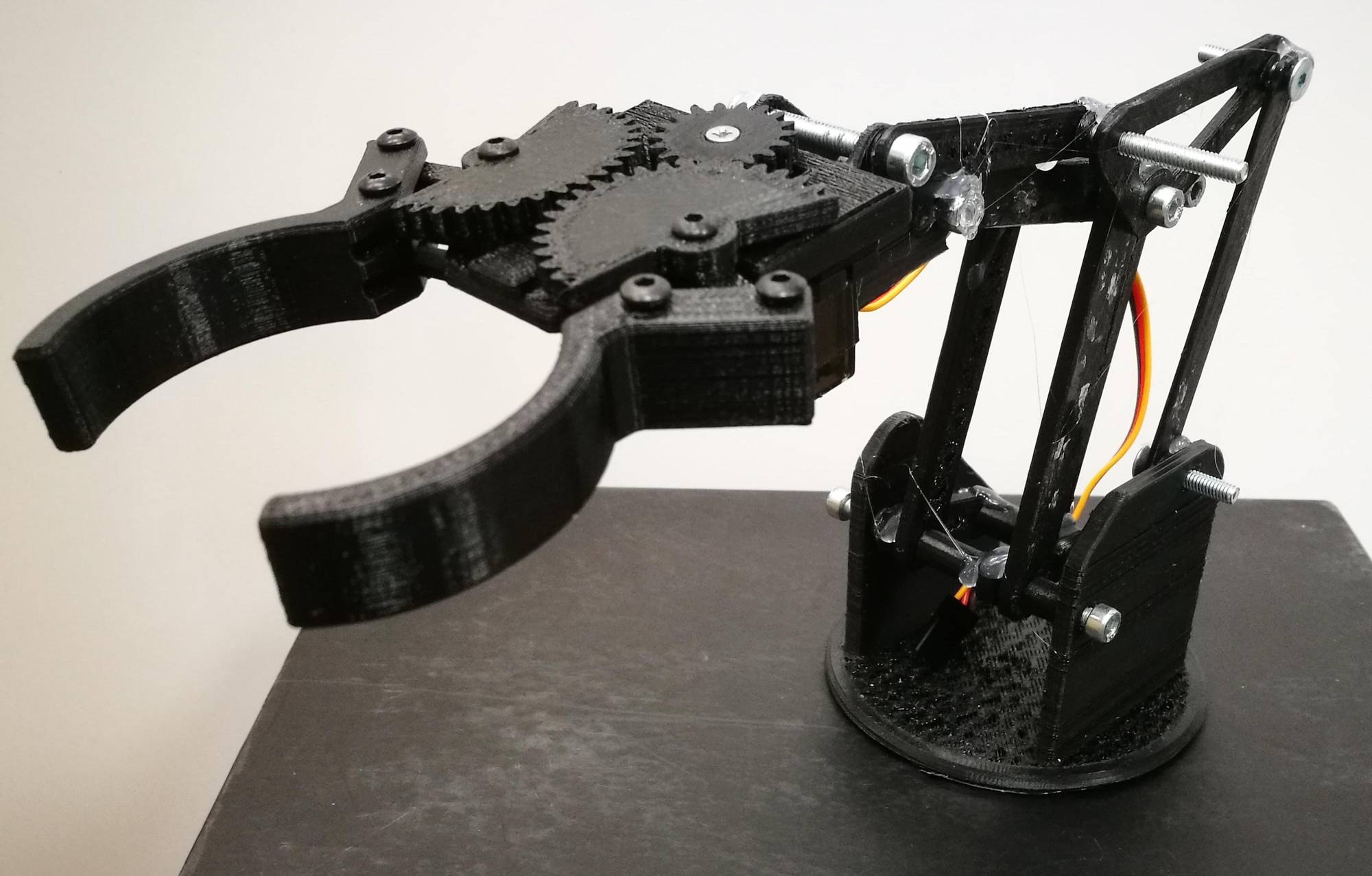
Next task was to design an arm to be able to handle the workpieces. The arm had to be able to reach the pieces on different positions. To make it easier to design while keeping the most flexibility we decided on a 2 DoF design. I modeled an arm that is about the suitable size for this robot based on a design found on GrabCAD. For the gripper I used the one that I designed in my thesis project.
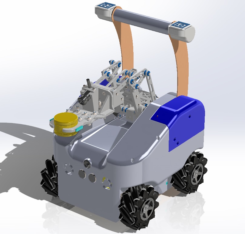
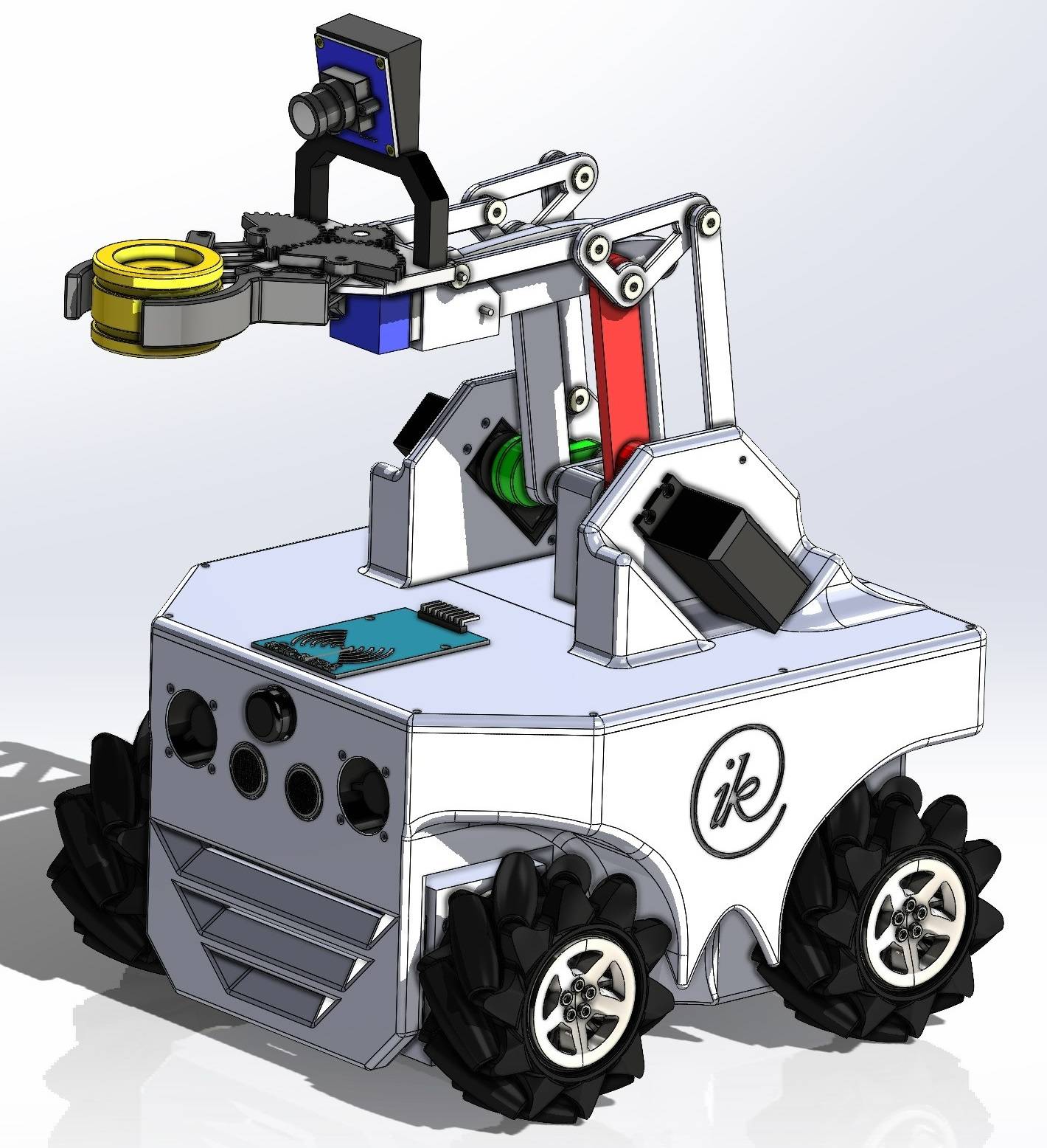
The second iteration brought a great change. The body got a complete rework and the arm got mounted on the top. The electronics was upgraded and got its mounts inside the body. The arduino as main computer was replaced with a Raspberry Pi and the first lines of the firmwares were written. The arm was also upgraded, dimensions were changed, motors got mounted and a camera was added.
At this point as the scale began to grow and I got some help. The firmware on the Raspberry was written by a colleague and was based on ROS. It was choosen as this colleague used it before and was familiar with it. The body got a visual touch up by a designer colleague.
At this point the robot was able to move around and the arm was able to pick up and place workpieces, but it had to be remote controlled to do so. The coleague writing the ROS code made a terminal interface and the wheels and arm could be controlled with the keyboard. (Raspberry and computer on same wifi and SSH into the Raspberry) Here we noticed the limits of the controller IC of the CNC shield, an 8-bit ARM MCU. It could not handle the speed of the motors and began to show weird artifacts at moderate speeds. Because of this I began the complete redesign of the electronics. Only thing that was kept was the Raspberry Pi.
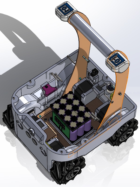
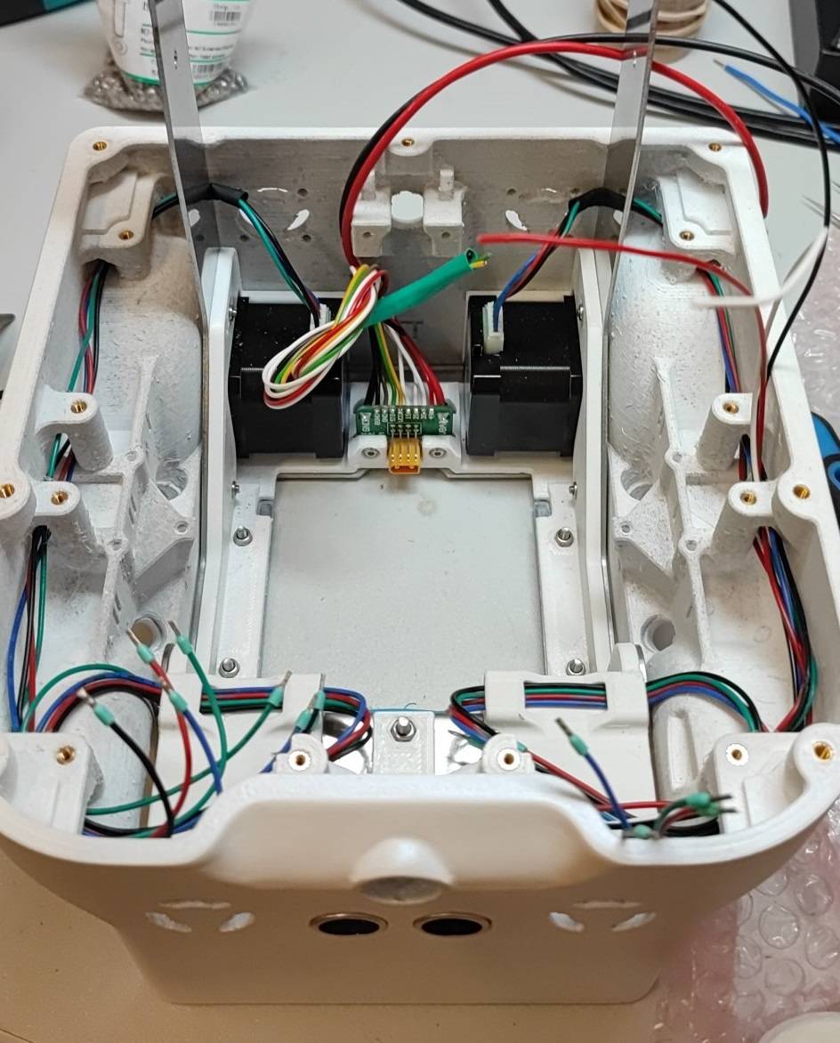
I designed a battery pack and made it to be quick-changable. It got a custom connector and a locking mechanism. The inside of the body was rearranged and the previously scattered electronic components all got integrated onto the PCB that got the name “MOBO” as in motherboard. While I was working on this, our designer made a new body shape. I modified this model to be able to fit the components and to be able to manufacture it. This version also introduced a metal frame for more rigidity and to carry the handle.
We needed to test the new panel and the robot’s movement in a more ergonomic way, so I decided to make use of my DualShock 4 controllers. We found a library that could be used to connect the controller to the Raspberry. Another colleague, also familiar with ROS wrote the code that I tested and fine tuned. This meant the maping of the buttons, scaling the analog inputs to the correct speed and such. Because of this I started learning about ROS too.
There were many problems with the first MOBO as it was a fairly complex design and was rushed. There were another two iterations and many problems were mitigated and even some new features added. The project slowly shifted from a hardware project into a software one. There was a lot of debugging, testing and sometimes smoke. At the end ten units were build with my final design. Sadly I did not make any pictures of them.
I left the company before the official closure of the project because personal reasons. The project was taken over by other colleagues.
As I was working on this project for six months intensively, I could write a lot more about it, but I don’t want to stretch this article too much.
